
 EN
EN English
 Español
 عربى
عربى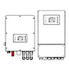

What Should You Look for When Choosing an Off-Grid Solar Inverter?
Content
- 1 What an Off-Grid Solar Inverter Does and Why It Is the System's Core Component
- 2 The Main Types of Off-Grid Solar Inverters and How They Differ
- 3 Key Specifications Explained: What the Numbers Actually Mean
- 4 How to Correctly Size an Off-Grid Inverter for Your System
- 5 Battery Compatibility: Matching the Inverter to Your Storage Technology
- 6 Solar Charge Controller Integration: MPPT vs. PWM
- 7 Features That Separate Quality Off-Grid Inverters From Budget Alternatives
- 8 Installation and Safety Requirements for Off-Grid Inverter Systems
What an Off-Grid Solar Inverter Does and Why It Is the System's Core Component
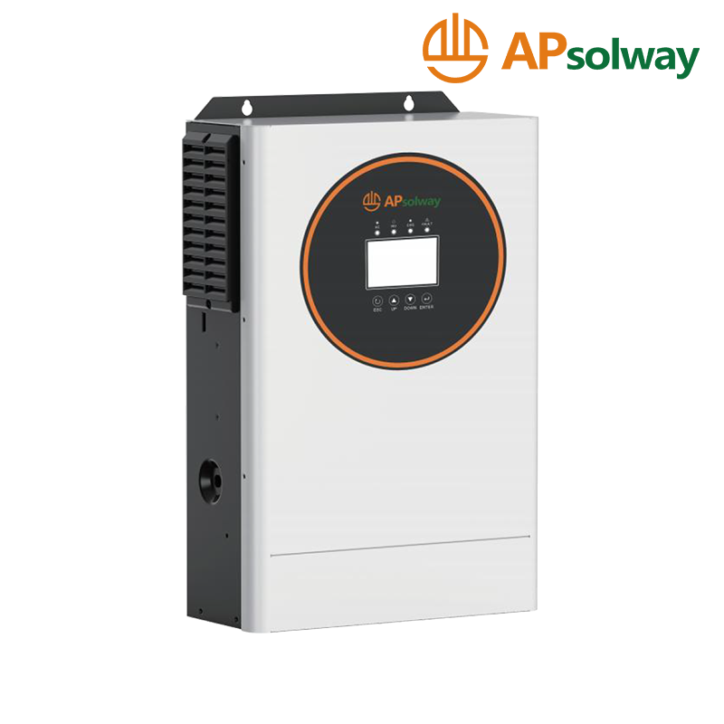
An off-grid solar inverter is the central processing unit of any stand-alone solar power system. Its fundamental job is to convert the direct current (DC) electricity stored in a battery bank into alternating current (AC) electricity at the voltage and frequency required by standard household or commercial appliances — typically 120V/60Hz in North America or 230V/50Hz in Europe and much of the rest of the world. Without an inverter, the DC power generated by solar panels and stored in batteries cannot power the vast majority of everyday loads, from refrigerators and lighting to power tools and computers.
In an off-grid system, the inverter carries responsibilities well beyond simple DC-to-AC conversion. It must manage the charging of the battery bank from solar panels, regulate the system voltage to protect batteries from overcharge and deep discharge, prioritize power sources intelligently when multiple inputs are available, and protect connected loads from voltage surges, frequency instability, and other power quality issues. In many modern off-grid inverter designs, the device also incorporates a solar charge controller, a battery charger for use with a backup generator, and comprehensive monitoring and communication functions — making it genuinely the brain of the entire off-grid power system rather than simply a conversion device.
The Main Types of Off-Grid Solar Inverters and How They Differ
Off-grid inverters are not a single product category — they encompass several distinct types that differ significantly in their output waveform quality, functionality, efficiency, and suitability for different applications. Understanding these differences is essential before making any purchasing decision.
Pure Sine Wave Inverters
Pure sine wave inverters produce an AC output waveform that is essentially identical in shape to the utility grid supply — a smooth, continuously varying sinusoidal wave. This output quality is compatible with all AC-powered devices without exception, including sensitive electronics such as variable-speed motor drives, medical equipment, audio amplifiers, and devices with active power factor correction in their power supplies. For any serious off-grid installation intended to power a full household or business load, pure sine wave output is the only appropriate specification. The electronics required to produce a true sine wave add cost compared to modified sine wave alternatives, but this premium is fully justified by the universal load compatibility and the prevention of energy waste, overheating, and premature failure in connected equipment.
Modified Sine Wave Inverters
Modified sine wave inverters produce a stepped, approximated waveform that resembles a square wave with intermediate voltage steps rather than a smooth sinusoidal curve. This waveform is adequate for resistive loads such as incandescent lighting and simple heating elements, but causes problems with inductive loads including motors, transformers, and compressors — which run hotter, less efficiently, and with greater noise. Devices with digital clocks, dimmers, and sensitive power supplies may malfunction or be damaged entirely. Modified sine wave inverters are significantly cheaper than pure sine wave units of equivalent power rating, but their limitations make them unsuitable for most practical off-grid residential or commercial installations. They retain niche relevance for very basic, budget-constrained applications with simple, resistive-only loads.
Hybrid and Multi-Function Inverter-Chargers
The most capable and widely specified category for serious off-grid installations is the inverter-charger — a unit that combines a pure sine wave inverter, a battery charger (for use with a generator or other AC source), and often a solar charge controller into a single integrated device. These units manage the flow of power between solar panels, battery storage, backup generator input, and AC loads automatically and intelligently, with user-configurable priorities for each power source. Advanced models communicate with battery management systems (BMS) in lithium battery banks, monitor system performance via smartphone apps or web interfaces, and support parallel stacking of multiple units to scale power capacity as needs grow.
Key Specifications Explained: What the Numbers Actually Mean
Inverter specification sheets contain a range of figures that are not always self-explanatory. Misreading or misapplying these numbers is a common source of undersized or inappropriately specified systems.
| Specification | What It Measures | Why It Matters |
| Continuous Power Rating (W) | Maximum sustained output power | Must exceed total simultaneous running load |
| Surge / Peak Power Rating (W) | Short-duration overload capacity | Must cover motor start-up inrush currents |
| Input Voltage Range (V DC) | Compatible battery bank voltage | Must match system battery voltage (12/24/48V) |
| No-Load / Standby Power (W) | Power consumed with no AC load connected | Directly reduces available battery runtime |
| Peak Efficiency (%) | Best-case conversion efficiency | Higher efficiency = less battery energy wasted |
| Transfer Time (ms) | Switch time from grid/generator to battery | Critical for sensitive electronics continuity |
The surge power rating deserves particular attention in off-grid system design. Electric motors — including those in refrigerator compressors, water pumps, air conditioning units, and power tools — draw two to seven times their running current for a brief period during start-up. An inverter that meets the running load requirement but cannot supply adequate surge current will either shut down on overload protection or produce voltage sag that prevents motors from starting successfully. Specifying an inverter with a surge rating at least three times the running wattage of the largest motor load in the system provides a reliable safety margin for most residential applications.
How to Correctly Size an Off-Grid Inverter for Your System
Undersizing an off-grid inverter is one of the most costly mistakes in system design — it results in frequent overload shutdowns, reduced equipment life, and the need for premature replacement. Oversizing wastes capital and increases standby power losses. A systematic sizing approach avoids both errors.
Step One: Calculate Total Running Load
List every AC appliance that may operate simultaneously during peak usage periods. Record the running wattage of each — not the maximum or starting wattage, but the steady-state power draw during normal operation. Sum these values to obtain the total simultaneous running load. Be realistic about which loads genuinely overlap in operation; cooking, heating, and laundry rarely occur at exactly the same moment as air conditioning and electric vehicle charging in a typical household, but in a worst-case design scenario, include all loads that could conceivably run together to ensure the system can handle genuine peak demand without compromise.
Step Two: Identify the Largest Motor Load
Identify the single highest-wattage motor load in the system — typically an air conditioner compressor, submersible water pump, or large refrigerator. Look up or measure its locked rotor amperage (LRA) or starting wattage, which is typically stated on the motor nameplate or available from the manufacturer's data sheet. The inverter's surge rating must comfortably exceed this starting wattage plus the combined running load of all other simultaneous loads. Add a 20–25% safety margin to the total to account for derating at elevated ambient temperatures and the inevitable load growth that occurs as systems are used and expanded over time.
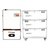
Step Three: Select Battery Bank Voltage
Battery bank voltage — typically 12V, 24V, or 48V — must be selected before choosing an inverter, as the two must be matched. Higher system voltages are strongly preferred for larger systems because they reduce the current flowing through cables for any given power level, allowing smaller wire gauges, lower resistive losses, and more cost-effective wiring. Systems above 2,000W continuous output should use 48V battery banks in nearly all cases. Systems below 1,000W can be practical at 24V, while 12V systems are generally only appropriate for very small loads under 600W where integration with 12V vehicle electrical systems is an additional requirement.
Battery Compatibility: Matching the Inverter to Your Storage Technology
The battery technology chosen for an off-grid system has direct implications for inverter selection, as different chemistries require fundamentally different charging profiles and have different voltage operating ranges and communication requirements.
- Flooded lead-acid batteries require a three-stage charging profile (bulk, absorption, float) with periodic equalization charges to prevent sulfation. The inverter-charger must support configurable absorption voltage and equalization parameters, and must include temperature compensation to adjust charging voltage based on battery temperature.
- AGM and gel lead-acid batteries use similar three-stage charging but with lower absorption voltages and no equalization requirement. Applying equalization voltage to these sealed batteries causes internal gassing and permanent damage; the inverter must allow equalization to be disabled entirely.
- Lithium iron phosphate (LiFePO4) batteries have a fundamentally different charging profile — they charge at constant current to a set voltage cutoff with no absorption stage — and require communication between the battery BMS and the inverter to implement charge cutoff and low-voltage disconnect correctly. For lithium battery installations, verify that the inverter either has a pre-configured lithium charging profile or supports CAN bus or RS-485 communication with the specific BMS being used.
- Nickel-iron and other alternative chemistries have their own specific requirements; always verify inverter compatibility with the battery manufacturer before finalizing equipment selection.
Solar Charge Controller Integration: MPPT vs. PWM
Many off-grid inverter-charger units incorporate a solar charge controller directly, eliminating the need for a separate device and simplifying system wiring. When evaluating integrated charge controller specifications, the technology type — MPPT or PWM — has a significant impact on system energy yield.
Maximum power point tracking (MPPT) charge controllers continuously calculate the optimal operating point on the solar panel's power curve and adjust the input voltage dynamically to extract maximum available power under all irradiance and temperature conditions. MPPT controllers typically harvest 20–30% more energy from a given panel array than PWM controllers, particularly in cold weather when panel open-circuit voltage is highest and when irradiance is variable due to partial cloud cover. For any system where maximizing energy yield is important — which describes virtually all serious off-grid installations — MPPT integration is strongly preferred. Pulse width modulation (PWM) controllers are simpler and cheaper but waste potential harvest by clamping the panel voltage down to near the battery voltage, foregoing the additional power available higher up the panel's power curve.
Features That Separate Quality Off-Grid Inverters From Budget Alternatives
The off-grid inverter market spans an enormous price range, from budget units with minimal features and uncertain reliability to professional-grade systems with comprehensive monitoring, scalability, and long warranty support. Understanding which features genuinely add value helps justify the investment in higher-quality equipment.
- Configurable load management and programmable relay outputs allow the inverter to automatically shed non-critical loads when battery state of charge drops below a threshold, extending runtime for priority circuits without requiring manual intervention.
- Generator auto-start output enables the inverter to automatically start a backup generator when battery state of charge drops below a set level, charge the batteries to a target level, then automatically shut the generator down — removing the need for manual generator management during periods of extended poor solar resource.
- Parallel and three-phase stacking capability allows multiple identical inverter units to be connected together to multiply power output capacity, providing a cost-effective path for future system expansion without replacing the original inverter.
- Remote monitoring via Ethernet, Wi-Fi, or cellular connection allows real-time system performance data — power flows, battery state of charge, solar yield, load consumption — to be viewed and managed from any location through a smartphone app or web browser dashboard.
- Comprehensive protection functions including over-voltage, under-voltage, over-temperature, short-circuit, and overload protection with automatic recovery prevent damage to both the inverter and connected loads during fault conditions.
- Long warranty terms from established manufacturers — typically five years for professional-grade equipment versus one to two years for budget alternatives — reflect both the confidence the manufacturer has in product reliability and the practical support available when issues occur during the system's operating life.
Installation and Safety Requirements for Off-Grid Inverter Systems
Off-grid solar inverter systems involve potentially lethal voltages on both the DC side — particularly with 48V lithium battery banks capable of delivering thousands of amperes of short-circuit current — and the 120V or 230V AC output side. Safe installation requires adherence to applicable electrical codes, use of correctly rated components throughout the system, and in most jurisdictions, work performed or inspected by a licensed electrician.
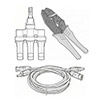
- DC cable sizing: DC cables between the battery bank and inverter carry the highest currents in the system. Use cables rated for the inverter's maximum DC input current with a minimum 25% safety margin, and keep cable runs as short as possible to minimize resistive voltage drop and energy loss.
- DC fusing and disconnect: Install an appropriately rated DC fuse or circuit breaker and a manual DC disconnect switch between the battery bank and inverter. This allows the inverter to be safely isolated for maintenance and provides overcurrent protection in the event of a wiring fault.
- AC output protection: The AC output of the inverter should feed a properly rated AC distribution panel with circuit breakers sized for each branch circuit. The inverter's AC output must not be connected to the utility grid without an approved anti-islanding mechanism — most pure off-grid inverters lack this and will cause dangerous backfeed if connected to utility lines.
- Ventilation and temperature management: Install the inverter in a location with adequate ventilation, protected from direct rainfall and direct sunlight, and within the manufacturer's specified ambient temperature operating range. Exceeding the maximum operating temperature triggers thermal derating or shutdown and accelerates component aging significantly.
Selecting and correctly installing an off-grid solar inverter is the single most consequential technical decision in any stand-alone solar power project. A well-matched, quality inverter that is properly sized for present and anticipated future loads, correctly specified for the battery chemistry in use, and carefully installed with appropriate safety measures will deliver reliable, grid-independent power for ten years or more. The investment in doing this component selection correctly at the outset — rather than accepting compromises driven by initial purchase price alone — pays dividends throughout the entire operational life of the system.
- Mp: +86-13819379269 / 15726870289
- Tel: +86-573-83705988
- Fax: +86-573-83705966
- E-mail: [email protected]
- Add: 10th Floor, Haizhou Star, Xiuzhou District, Jiaxing City, Zhejiang, China 314000
 Privacy
Solar Inverters Manufacturers
Privacy
Solar Inverters Manufacturers