
 EN
EN English
 Español
 عربى
عربى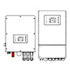

How Do You Choose the Right Solar Off-Grid Inverter for a Reliable Standalone Power System?
Content
- 1 What Is a Solar Off-Grid Inverter and How Does It Work?
- 2 Types of Solar Off-Grid Inverters
- 3 Key Specifications and What They Mean in Practice
- 4 Sizing a Solar Off-Grid Inverter Correctly
- 5 Battery Compatibility and Charging Integration
- 6 Installation, Safety, and Protection Features
- 7 Monitoring, Remote Management, and System Optimization
What Is a Solar Off-Grid Inverter and How Does It Work?
A solar off-grid inverter is the central power conversion device in a standalone photovoltaic system that operates independently from the utility grid. Its primary function is to convert the direct current (DC) electricity generated by solar panels — and stored in a battery bank — into alternating current (AC) electricity at the voltage and frequency required by standard household or commercial appliances. In an off-grid system, there is no grid connection to fall back on, which means the inverter must manage all aspects of power delivery autonomously: regulating output voltage, maintaining frequency stability, protecting connected loads from faults, and coordinating with the battery system and solar charge controller to ensure a continuous, reliable supply regardless of solar availability or load fluctuation.
Unlike grid-tied inverters — which synchronize their output to the mains and shut down automatically when the grid fails — off-grid inverters are designed to operate as the sole power source for the system. They must handle the full dynamic range of load behavior, from the negligible standby draw of a single LED light to the high inrush current demand of a motor starting or a refrigerator compressor cycling on. Many modern off-grid inverters integrate the charge controller, battery management interface, and inverter functions into a single unit, often described as an inverter-charger, solar inverter-charger, or hybrid inverter depending on whether they also include grid or generator input capability for supplemental charging.
Types of Solar Off-Grid Inverters
Not all off-grid inverters use the same output waveform or internal architecture, and the differences between types have significant practical consequences for the loads they can power reliably and efficiently.
Pure Sine Wave Inverters
Pure sine wave inverters produce an AC output waveform that is electronically shaped to match the smooth sinusoidal profile of utility grid power, with total harmonic distortion (THD) typically below 3%. This output is compatible with virtually every AC load, including sensitive electronics such as variable-speed motor drives, medical equipment, audio amplifiers, and switch-mode power supplies found in computers and televisions. Inductive loads like pumps, air conditioners, and refrigerator compressors run cooler, quieter, and more efficiently on pure sine wave power because the clean waveform minimizes the eddy current losses and acoustic noise that modified sine wave power induces in motor windings. For any off-grid system intended to power a full household or support sensitive equipment, a pure sine wave inverter is the only technically appropriate choice.
Modified Sine Wave Inverters
Modified sine wave inverters — sometimes called modified square wave inverters — produce a stepped approximation of a sine wave using a simpler switching circuit. The output alternates between positive, zero, and negative voltage levels in a pattern that delivers the correct RMS voltage and frequency, but with significantly higher harmonic distortion, typically 25–45% THD. This waveform is adequate for resistive loads such as incandescent lighting, electric heating elements, and simple battery chargers. However, it causes efficiency losses and heat generation in motor-driven appliances, can interfere with digital clocks and dimmers, and may damage or fail to operate certain electronic devices that rely on zero-crossing detection or power factor correction. Modified sine wave inverters are lower in cost but represent a false economy in most residential off-grid applications where diverse load types are present.
Inverter-Chargers and Hybrid Off-Grid Inverters
Inverter-chargers combine a pure sine wave inverter with a multi-stage battery charger and an automatic transfer switch in a single integrated unit. When a generator or supplemental AC source is connected, the inverter-charger switches to pass-through mode, powering the loads directly from the AC source while simultaneously charging the battery bank at a programmable rate. When the external source is removed or unavailable, the transfer switch engages and the unit reverts to inverter mode, drawing from the batteries. This architecture is particularly practical in off-grid cabins, remote worksites, and island-mode backup systems where solar alone cannot always meet demand and a generator provides supplemental energy during extended low-irradiance periods. Hybrid inverters add a solar MPPT (maximum power point tracking) charge controller input directly to the unit, allowing the panel array, battery bank, load output, and optional generator input to all be managed through a single device with a unified monitoring interface.
Key Specifications and What They Mean in Practice
Selecting a solar off-grid inverter based on marketing claims alone leads to undersized or mismatched systems. Each specification on the datasheet has a direct practical consequence for system performance and reliability. The following table summarizes the most critical parameters:
| Specification | What It Defines | Practical Implication |
| Continuous Power Rating (W or VA) | Maximum sustained output | Must exceed total simultaneous load wattage with 20–25% safety margin |
| Peak / Surge Power (W) | Short-duration overload capacity | Must handle motor start inrush (typically 3–7× running watts) without tripping |
| DC Input Voltage Range | Compatible battery bank voltage | Must match battery system: 12V, 24V, 48V systems have different current demands |
| AC Output Voltage and Frequency | Output compatibility with loads | Must match regional standard: 120V/60Hz (North America) or 230V/50Hz (Europe, Asia) |
| Conversion Efficiency (%) | DC-to-AC power conversion loss | Higher efficiency (93–98%) reduces battery drain and heat generation significantly |
| Idle / No-Load Consumption (W) | Standby power draw | Low idle draw (5–15W) critical in systems with long overnight low-load periods |
| THD (%) | Output waveform quality | Below 3% required for sensitive electronics and motor-driven appliances |
| MPPT Input Range (V) — if integrated | Compatible PV array voltage | Must accommodate panel string Voc at minimum temperature without exceeding maximum input |
Sizing a Solar Off-Grid Inverter Correctly
Inverter sizing is one of the most consequential decisions in off-grid system design, and both undersizing and oversizing carry significant costs. An undersized inverter will trip under peak load demand, fail to start motor loads, and degrade prematurely from thermal stress. An oversized inverter operates at chronically low load fractions where conversion efficiency drops and idle power consumption becomes a disproportionate drain on the battery bank overnight.
Calculating Continuous Load Requirements
Begin by auditing every AC load that might operate simultaneously in the system. List each device's power consumption in watts, note the hours of daily use, and identify which devices could realistically run at the same time. The sum of simultaneously operating loads represents the minimum continuous power rating the inverter must sustain. Add a 20–25% safety margin to this figure to account for efficiency losses, measurement inaccuracies, and future load additions. For example, if simultaneous loads total 1,800W, the inverter continuous rating should be at least 2,200–2,400W.
Accounting for Surge and Inrush Current
Motor-driven appliances — refrigerators, water pumps, air conditioners, power tools — draw three to seven times their running wattage for a fraction of a second when starting. The inverter's surge or peak power rating must comfortably exceed this inrush demand, or the unit will trip its overload protection and drop the load. A refrigerator rated at 150W running power may demand 900–1,050W for 0.5–2 seconds at startup. If a water pump (250W running, 1,500W surge) and refrigerator start simultaneously — an unlikely but not impossible scenario — the total surge demand could reach 2,550W. The inverter must handle this without shutdown. Manufacturers specify surge ratings at defined durations (typically 5–30 seconds); verify that the surge rating applies at a time duration relevant to the motor loads in your system.
Matching DC Voltage to Battery Bank Architecture
The DC input voltage of the inverter must match the nominal voltage of the battery bank. For small systems below 1,000W, a 12V battery bank is common and practical. Systems between 1,000W and 3,000W typically use 24V to reduce DC cable currents and losses. Systems above 3,000W should use 48V battery banks — a 3,000W load at 12V requires 250A DC current, demanding very heavy cabling and causing significant resistive losses, while the same load at 48V requires only 62.5A, making the wiring practical and efficient. Most quality off-grid inverters above 2,000W are designed for 48V input, and lithium iron phosphate (LiFePO4) battery systems — increasingly the preferred chemistry for off-grid installations — are commonly configured in 48V nominal architecture.
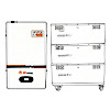
Battery Compatibility and Charging Integration
The relationship between the off-grid inverter and the battery bank is the most operationally critical interface in the entire system. Incorrect charging parameters will undercharge and sulfate lead-acid batteries, or overcharge and thermally damage lithium cells. Modern off-grid inverter-chargers offer programmable charge profiles that can be configured for flooded lead-acid, AGM, gel, or lithium battery chemistries, with adjustable absorption voltage, float voltage, equalization voltage, and charge current limits.
- Lead-acid compatibility: Flooded, AGM, and gel batteries require three-stage charging (bulk, absorption, float) with chemistry-specific voltage setpoints. Flooded batteries also benefit from periodic equalization charges that the inverter-charger must be able to deliver on a programmable schedule. Incorrect float voltage — even by 0.1–0.2V per cell — accelerates plate corrosion and water loss over months of operation.
- Lithium iron phosphate (LiFePO4) integration: LiFePO4 batteries require precise charge voltage cutoff (typically 3.65V per cell, or 58.4V for a 48V 16S pack) and must not be trickle-charged at float voltage like lead-acid. The inverter must communicate with or be programmed to respect the battery management system (BMS) charge and discharge cutoff signals. Many premium off-grid inverters now include CAN bus or RS485 communication ports for direct BMS integration, enabling the BMS to command charge current reduction or disconnection without relying solely on voltage thresholds.
- Low voltage disconnect (LVD) settings: The inverter must be programmed to disconnect the AC output before the battery voltage drops to a level that would damage the cells or prevent the system from restarting with available solar power. Setting LVD too low risks deep discharge damage; setting it too high wastes usable capacity. For LiFePO4, a common LVD setpoint is 44–46V (for a 48V nominal system); for AGM, 47–48V is typical.
Installation, Safety, and Protection Features
A solar off-grid inverter operates at both high DC voltages (up to 60V for 48V systems, higher for MPPT inputs) and high AC voltages (120V or 230V), presenting serious shock and fire hazards if installed incorrectly. Proper installation practice and attention to built-in protection features are essential for safe long-term operation.
- DC fusing and disconnects: Every inverter installation requires appropriately rated DC fusing or a circuit breaker between the battery bank and the inverter's DC input terminals, positioned as close to the battery as physically practical. The fuse rating must protect the DC cable from overcurrent while exceeding the inverter's maximum DC input current under full load. A DC disconnect switch allows safe isolation of the inverter from the battery without removing fuses under load.
- AC output protection: The inverter's AC output should feed a dedicated distribution panel or sub-panel with individual circuit breakers for each load circuit. This allows selective load shedding during low battery conditions and provides overload protection for individual branch circuits independently of the inverter's own protection systems.
- Built-in inverter protections: Quality off-grid inverters include automatic protection against over-temperature, overload, short circuit, low DC input voltage, high DC input voltage, and reverse polarity. Verify that the unit's datasheet explicitly lists these protections and specifies the response time and reset behavior for each, as the protection architecture significantly affects system reliability in fault conditions.
- Grounding and bonding: The inverter chassis, AC output neutral, and DC negative (in some system configurations) must be properly grounded and bonded according to the applicable electrical code — NEC Article 690 in the United States, or equivalent national standards elsewhere. Improper grounding creates shock hazards and can cause ground fault protection devices to malfunction, leaving faults undetected.
- Ventilation and ambient temperature: Class D inverters and even high-efficiency Class D designs generate heat that must be dissipated to maintain rated performance. Install the inverter in a ventilated enclosure or location where ambient temperature does not exceed the manufacturer's rated maximum — typically 40–50°C. Inverters mounted in sealed battery enclosures or unventilated outdoor boxes frequently experience premature thermal shutdowns and accelerated component aging.
Monitoring, Remote Management, and System Optimization
Modern solar off-grid inverters increasingly offer data logging, remote monitoring, and remote configuration capabilities that allow system owners and installers to track performance, diagnose problems, and optimize settings without physical site visits. Communication interfaces vary by manufacturer and product tier, but the most common implementations include Wi-Fi or Ethernet connectivity to cloud monitoring platforms, Bluetooth for local configuration via smartphone app, RS232 or USB ports for computer-based configuration software, and RS485 or CAN bus for integration with battery BMS and external energy management controllers.
Effective monitoring of an off-grid system should track daily solar harvest (kWh), battery state of charge (SOC) profile throughout the day, AC load consumption by hour, and any fault or protection events logged by the inverter. Reviewing this data over weeks and seasons reveals patterns that allow system optimization — adjusting load schedules to align with peak solar hours, identifying appliances with unexpectedly high consumption, and detecting early signs of battery capacity degradation before a failure disrupts power supply. For remote installations where travel for diagnosis is expensive or impractical, remote monitoring capability transitions from a convenience feature to a critical operational tool that directly affects the reliability and cost-effectiveness of the off-grid system over its full service life.
- Mp: +86-13819379269 / 15726870289
- Tel: +86-573-83705988
- Fax: +86-573-83705966
- E-mail: [email protected]
- Add: 10th Floor, Haizhou Star, Xiuzhou District, Jiaxing City, Zhejiang, China 314000
 Privacy
Solar Inverters Manufacturers
Privacy
Solar Inverters Manufacturers