
 EN
EN English
 Español
 عربى
عربى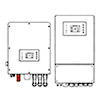

How Do You Choose the Right Off-Grid Solar Inverter for Your System?
Content
- 1 What an Off-Grid Solar Inverter Does and Why It Is Central to Your System
- 2 Types of Off-Grid Solar Inverters
- 3 Pure Sine Wave vs Modified Sine Wave: A Practical Comparison
- 4 How to Size an Off-Grid Inverter Correctly
- 5 Battery Voltage and Inverter Compatibility
- 6 Key Specifications to Evaluate When Comparing Inverters
- 7 Battery Compatibility: Matching Inverter to Battery Chemistry
- 8 Installation, Cabling, and Safety Considerations
What an Off-Grid Solar Inverter Does and Why It Is Central to Your System
An off-grid solar inverter is the nerve centre of any standalone solar power system. Its primary function is to convert the direct current (DC) electricity stored in your battery bank into alternating current (AC) electricity — the form required by virtually all household appliances, power tools, lighting circuits, and electronic devices. Without an inverter, the energy captured by your solar panels and stored in your batteries would be inaccessible to standard AC loads. In an off-grid system, there is no utility grid to fall back on when your own generation or storage falls short, which makes the inverter's reliability, efficiency, and capacity sizing more consequential than in any other solar application.
Modern off-grid inverters do considerably more than simple DC-to-AC conversion. Most units integrate battery charging circuitry, solar charge control, system monitoring, and load management into a single device — functions that in earlier generations of off-grid systems required separate components. This integration simplifies installation, reduces points of failure, and allows the inverter to optimise energy flow across the whole system based on battery state of charge, solar generation availability, and load demand simultaneously. Understanding how these functions work together is essential to selecting an inverter that will perform reliably over the 10–15 year service life expected of quality off-grid equipment.
Types of Off-Grid Solar Inverters
Pure Sine Wave Inverters
Pure sine wave inverters produce an AC output waveform that is electrically identical — or very close — to the smooth sinusoidal waveform supplied by a utility grid. The output voltage traces a clean, continuous curve through its positive and negative cycles, with total harmonic distortion (THD) typically below 3% in quality units. This waveform is compatible with every category of AC load: inductive motor loads (refrigerators, air conditioners, water pumps, power tools), sensitive electronics (computers, televisions, audio equipment, medical devices), and devices with internal power supplies that are intolerant of waveform distortion. Pure sine wave output is the correct specification for any off-grid system that will power a normal household load mix, and it is the only waveform type that should be considered for systems incorporating motor-driven appliances or sensitive electronics. The cost premium over modified sine wave units is meaningful but fully justified by compatibility and load safety.
Modified Sine Wave Inverters
Modified sine wave inverters produce a stepped, approximated waveform — a square wave with an intermediate zero-voltage step — rather than a true sinusoidal output. This waveform has a THD typically in the range of 20–40%, which creates significant problems for many categories of load. Induction motors running on modified sine wave power operate less efficiently, run hotter, and experience accelerated wear because the harmonic content of the waveform creates additional heating in the motor windings. Devices with capacitor-input power supplies — virtually all modern electronics — may produce audible buzz, overheat, or fail prematurely. Certain medical equipment, variable-speed drives, and audio amplifiers are incompatible with modified sine wave power entirely. Modified sine wave inverters are substantially cheaper than pure sine wave units at equivalent power ratings, but their appropriate use cases are limited to resistive loads such as incandescent lighting, simple heating elements, and basic battery chargers where waveform quality is not critical.
Inverter-Chargers (Hybrid Off-Grid Inverters)
Inverter-chargers combine a pure sine wave inverter with a multi-stage battery charger in a single unit, and many models also incorporate a solar charge controller (MPPT or PWM) to manage input from solar panels directly. When an alternative AC source is available — a generator, a shore power connection at a marina, or a temporary grid connection — the inverter-charger switches to charge mode and simultaneously supplies the AC loads from the incoming power source, bypassing the battery. When the alternative source is removed or fails, it switches back to inverter mode seamlessly, typically in under 20 milliseconds — a transition fast enough that most sensitive electronics do not interrupt. This architecture is the standard specification for serious off-grid residential systems, remote cabins, and mobile applications such as marine and motorhome installations, because it handles the full energy management workflow within a single, integrated device.
Pure Sine Wave vs Modified Sine Wave: A Practical Comparison
| Factor | Pure Sine Wave | Modified Sine Wave |
| Waveform THD | <3% | 20–40% |
| Motor compatibility | Full compatibility | Reduced efficiency, heat risk |
| Sensitive electronics | Safe for all devices | Risk of damage or malfunction |
| Medical devices | Compatible | Not recommended |
| Cost | Higher | Lower |
| Best application | All off-grid residential systems | Simple resistive loads only |
How to Size an Off-Grid Inverter Correctly
Inverter sizing is one of the most common sources of system underperformance and premature equipment failure in off-grid installations. Undersizing the inverter causes it to operate continuously at or near its thermal limit, accelerating component degradation and triggering overload shutdowns at inconvenient moments. Oversizing the inverter wastes capital expenditure and increases idle power consumption — the power the inverter draws simply to remain powered on with no load connected, which can be 20–50 watts in larger units and represents a meaningful daily parasitic drain on a battery bank.
The correct sizing process begins with a complete load audit: listing every AC appliance and device that will be connected to the inverter, its rated power in watts, and its typical daily operating hours. Sum the instantaneous wattages of all loads that could run simultaneously to establish the continuous power requirement — this is the minimum continuous power rating the inverter must exceed. Next, identify the largest single motor-driven load in the system (refrigerator, water pump, air conditioner, or power tool) and check its starting surge current requirement. Induction motors draw two to seven times their running wattage for 50–500 milliseconds at startup, and the inverter must supply this surge without triggering its overload protection. The inverter's surge capacity rating — typically expressed as a multiple of its continuous rating (e.g., 2× for 10 seconds) — must exceed this starting load requirement.
As a practical rule, add a 25% margin to the calculated continuous load requirement when selecting inverter size. This margin accommodates simultaneous operation of loads not anticipated in the initial audit, ensures the inverter operates comfortably below its thermal limit during normal use, and provides headroom for load growth as the system expands. A household with a calculated peak simultaneous load of 2,400 watts should select a 3,000-watt continuous rated inverter as the minimum specification.
Battery Voltage and Inverter Compatibility
Off-grid inverters are designed to operate from a specific DC input voltage that must match the system battery bank voltage. Common system voltages are 12V, 24V, and 48V, with 48V being the preferred specification for any system above approximately 2,000 watts continuous output. The relationship between system voltage and inverter power rating is constrained by current — at a given power level, doubling the system voltage halves the current flowing through the DC wiring and the inverter's internal components. This has profound practical implications: a 3,000-watt inverter operating from a 12V battery bank draws 250 amps at full load, requiring very heavy copper cable (2/0 AWG or larger) and producing significant resistive losses over even short cable runs. The same inverter operating from a 48V bank draws only 62.5 amps, manageable with 6 AWG cable with substantially reduced losses.
For small systems powering limited 12V-native loads in caravans, boats, or small cabins — typically below 1,000 watts — a 12V system is practical. Systems powering a normal household load mix should be designed at 48V from the outset. Attempting to retrofit a 12V system to higher power levels after initial installation is expensive and often impractical because the battery bank, cabling, and charge controllers must all be replaced.
Key Specifications to Evaluate When Comparing Inverters
- Continuous power rating (watts): The power the inverter can supply indefinitely without thermal derating. This is the primary sizing specification and must exceed your calculated peak simultaneous load with margin.
- Surge capacity: The peak power the inverter can supply for short periods (typically 5–30 seconds) to start motor loads. Express as a wattage figure and verify it exceeds the starting surge of your largest motor load.
- Conversion efficiency: The percentage of DC input energy converted to AC output energy at a given load level. Quality pure sine wave inverters achieve 93–97% efficiency at 50–75% of rated load. Efficiency curves show performance across the load range — select an inverter whose peak efficiency point aligns with your typical operating load.
- Idle (no-load) power consumption: The power the inverter consumes while energised but with no load connected. In systems where the inverter runs continuously, this figure — typically 15–50 watts depending on size — accumulates to a meaningful daily energy drain. Search mode (auto-sleep) feature reduces idle draw by 70–90% by switching the inverter to a low-power search pulse when no load is detected.
- DC input voltage range: The range of battery voltages over which the inverter operates correctly. A wide input range (e.g., 42–60V for a nominal 48V system) accommodates the full charge cycle of the battery bank, from absorption voltage at full charge to the low-voltage cutoff that protects against deep discharge.
- Low-voltage cutoff: The battery voltage at which the inverter automatically shuts down to prevent damaging deep discharge. This must be set appropriately for the battery chemistry — lead-acid, lithium iron phosphate (LiFePO4), and other chemistries have different safe discharge limits, and the inverter's cutoff must be configurable to match.
- Output frequency: Must match the local grid standard — 50 Hz in Europe, Australia, Asia, and Africa; 60 Hz in North America and parts of South America. Most quality inverters allow frequency selection during commissioning.
- Protection features: Verify the inverter includes overload protection, short-circuit protection, over-temperature shutdown with automatic restart, under-voltage and over-voltage battery protection, and reverse polarity protection. These safeguards protect both the inverter and connected loads from damage under fault conditions.
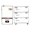
Battery Compatibility: Matching Inverter to Battery Chemistry
The emergence of lithium iron phosphate (LiFePO4) batteries as the dominant battery technology in new off-grid installations has introduced compatibility requirements that must be addressed at the inverter selection stage. LiFePO4 batteries have a substantially different charge voltage profile from lead-acid — a flatter discharge curve, a higher full-charge voltage per cell, and a strict requirement for a battery management system (BMS) that communicates with the inverter to coordinate charge and discharge parameters. Many modern inverter-chargers support communication with LiFePO4 battery BMS units via CAN bus, RS485, or proprietary protocols, allowing the inverter to receive real-time state-of-charge data and adjust its behaviour accordingly — halting charging when the BMS reports full charge, and shedding loads or shutting down when the BMS reports critically low state of charge.
If you are specifying an off-grid system with LiFePO4 batteries, verify explicitly that the selected inverter supports your battery brand's communication protocol, or that the battery BMS includes an external low-voltage relay output that can trigger the inverter's external shutdown input. Connecting a LiFePO4 battery bank to an inverter with charge parameters set for lead-acid without correct BMS integration risks overcharging the battery or failing to prevent damaging deep discharge — failures that can permanently damage a battery bank representing a significant portion of the total system investment.
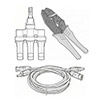
Installation, Cabling, and Safety Considerations
Correct installation practice is as important as correct inverter selection. The DC cables connecting the battery bank to the inverter should be as short as possible — ideally under one metre — and sized for the maximum DC current draw at full inverter output with no more than 0.5V drop across the cable run. Longer runs or undersized cables introduce resistance that reduces efficiency, creates heat, and can cause inverter undervoltage shutdowns during peak loads even when the battery is at adequate state of charge. Install a correctly rated fuse or DC circuit breaker on the positive DC cable within 30 cm of the battery terminal to protect against short circuit faults in the DC wiring.
Mount the inverter in a dry, ventilated location with clearance around the cooling vents specified in the manufacturer's installation guide — typically a minimum of 150–200 mm on all sides with air intake and exhaust paths that allow natural convection or forced cooling airflow. Inverters mounted in sealed compartments without airflow will operate at elevated temperature, reducing efficiency and service life. In mobile applications (marine, motorhome), secure the inverter against vibration using rubber-isolated mounts and verify the installation meets any applicable maritime or vehicle electrical standards for your jurisdiction before commissioning the system.
- Mp: +86-13819379269 / 15726870289
- Tel: +86-573-83705988
- Fax: +86-573-83705966
- E-mail: [email protected]
- Add: 10th Floor, Haizhou Star, Xiuzhou District, Jiaxing City, Zhejiang, China 314000
 Privacy
Solar Inverters Manufacturers
Privacy
Solar Inverters Manufacturers